Light Duty and Medium Duty Dump Kit Installation Overview
PIERCE Light Duty Dump Bed Kit Installation Guide
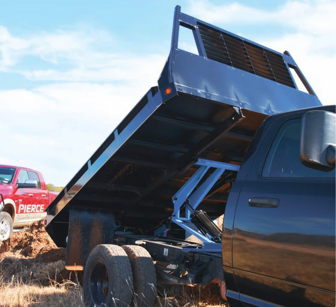
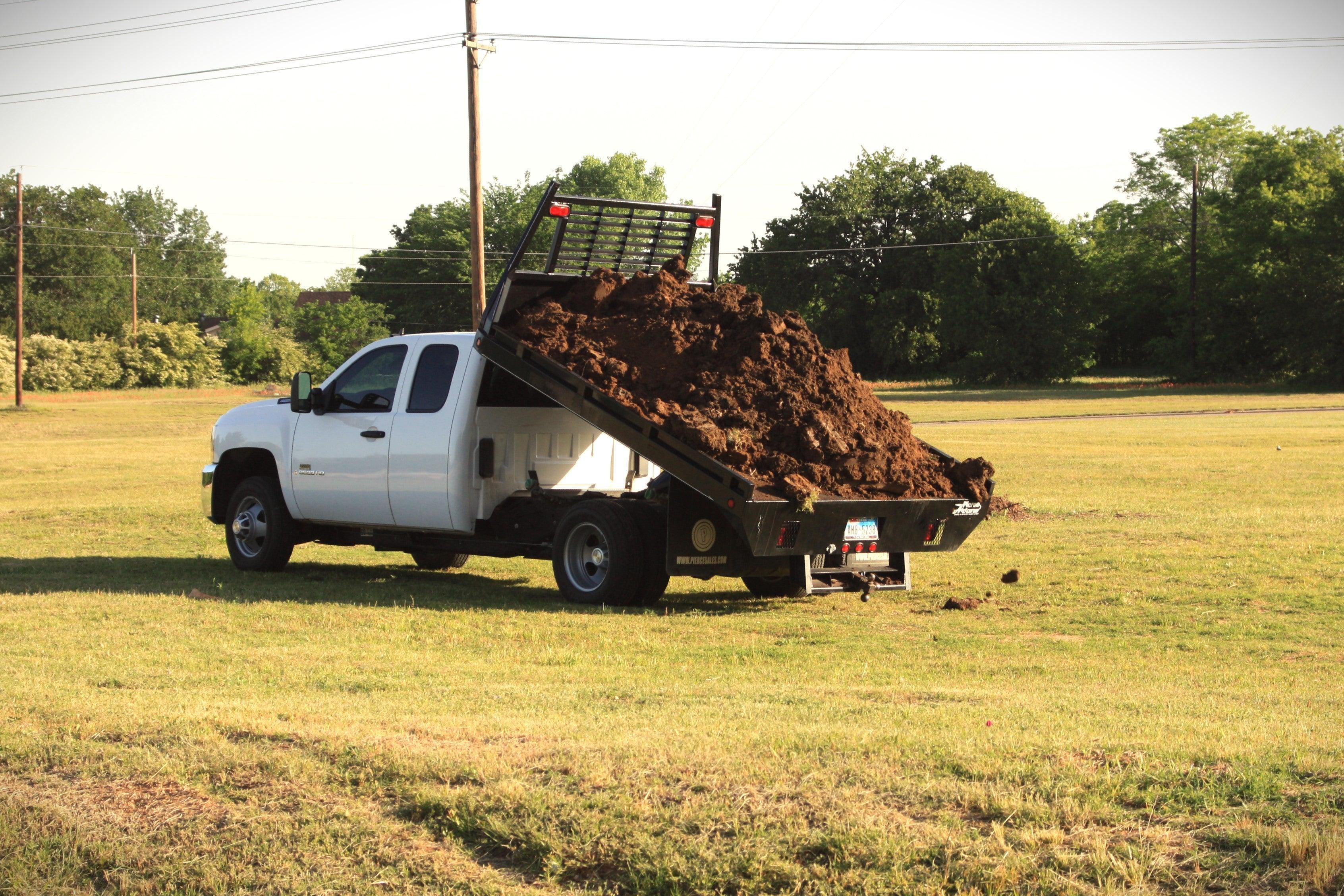
This guide provides an overview of installing the PIERCE Light Duty Dump Bed Kit on a Chevrolet cab and chassis with a 60-inch cab-to-axle measurement. The installation uses a custom 10-foot bed to accommodate the rear hinges of the dump hoist kit, slightly longer than the standard 9-foot bed for this truck size.
Important Note: This installation requires expertise and proper equipment. If you lack the necessary skills or tools, consult a licensed converter to ensure safety and avoid damage to your equipment. Modifications may vary by truck make and model. For assistance, contact PIERCE phone support.
Part 1: Pre-Installation and Measurements
Shortening the Chassis
To maximize bed overhang for enhanced lifting strength, shorten the chassis frame as follows:
-
Remove taillights and inspect the chassis rear.
-
Cut the frame near the rearmost cross member at a 45-degree angle to allow pin clearance while providing metal for welding or bolting the rear hinge.
-
Weld the rear hinge to the frame, avoiding welds forward of the rear frame hanger to prevent cracks or weak spots. Bolt the front of the frame hanger to the chassis.
Rear Hinge Placement
-
Position the rear hinge in the slot between the outer frame and the cross member.
-
Ensure sufficient clearance for hinge pins and secure the hinge to the chassis.
Scissor Assembly Placement
-
Measure 5’8” to 6’6” from the rear hinge to the scissor assembly’s cross member pin.
-
For this installation, place the scissor assembly at 5’11.5” due to clearance issues with the front fuel tank filler hose.
-
Bolt L-brackets to the frame using existing overload spring perch bolt holes, sandwiching them with longer bolts to secure the scissor assembly.
Bed Height Considerations
-
Account for the fuel filler hose thickness (specific to Chevrolet; Ford/Dodge may allow lower bed placement).
-
Maintain a 2-inch gap between the bed sill and chassis frame to ensure clearance for the fuel filler hose in the lowered position.
Cross Member Modifications
-
Trim the cross member to fit the 34-inch frame width, allowing room to weld it to the L-brackets without damaging the truck frame.
-
Use existing bolt holes to secure the L-brackets, preserving chassis integrity.
Front Frame Hinges
-
Add spacers if needed to achieve proper clearance between the chassis frame and bed sill.
-
Trim the sill support to fit inside the bed’s main runner for optimal alignment.
Verifying Measurements
-
The bed uses a 4-inch sill and a 3-inch cross member, totaling 7 inches from the bed deck to the chassis.
-
With a 2.5-inch spacer at the rear hinges, the overall height is 9.5–10 inches, providing 1–1.5 inches of clearance for the fuel tank vent.
-
Adjust the scissor assembly position if needed, noting constraints like fuel tank placement.
Part 2: Wiring Connections
Wiring Kit Components
-
Positive (red) and negative (black) battery cables for direct battery connection.
-
Hydraulic hose, switch, wiring, and hardware for pump mounting.
Pump Installation
-
Fabricate a bracket to mount the pump in a safe location (e.g., inside/outside the frame, behind the seat, or in a weather-protected area).
-
Use Teflon paste or suitable pipe sealant for the 90-degree fitting. Remove the control valve solenoid coil (black plastic square) to install the fitting, ensuring the hose avoids contact with the muffler, tailpipe, or moving parts.
-
Reattach the solenoid coil after securing the fitting.
Wiring Connections
Connect the following wires to the pump:
-
Yellow: To the coil for the down function.
-
Green: To the small post on the black motor solenoid.
-
Red: To the power supply post on the black motor solenoid (closest to the truck frame).
-
Black: To the ground post on the motor.
-
Note: The brown wire is not used in this installation, as the customer requested operation only when the ignition is on for safety.
Battery Connections
-
Connect the red positive cable to a 150-amp breaker, then to the battery.
-
Secure the negative cable directly to the battery for a reliable ground.
-
Use #4 welding cables (included) and secure them every 12–15 inches to prevent wear from wind or debris.
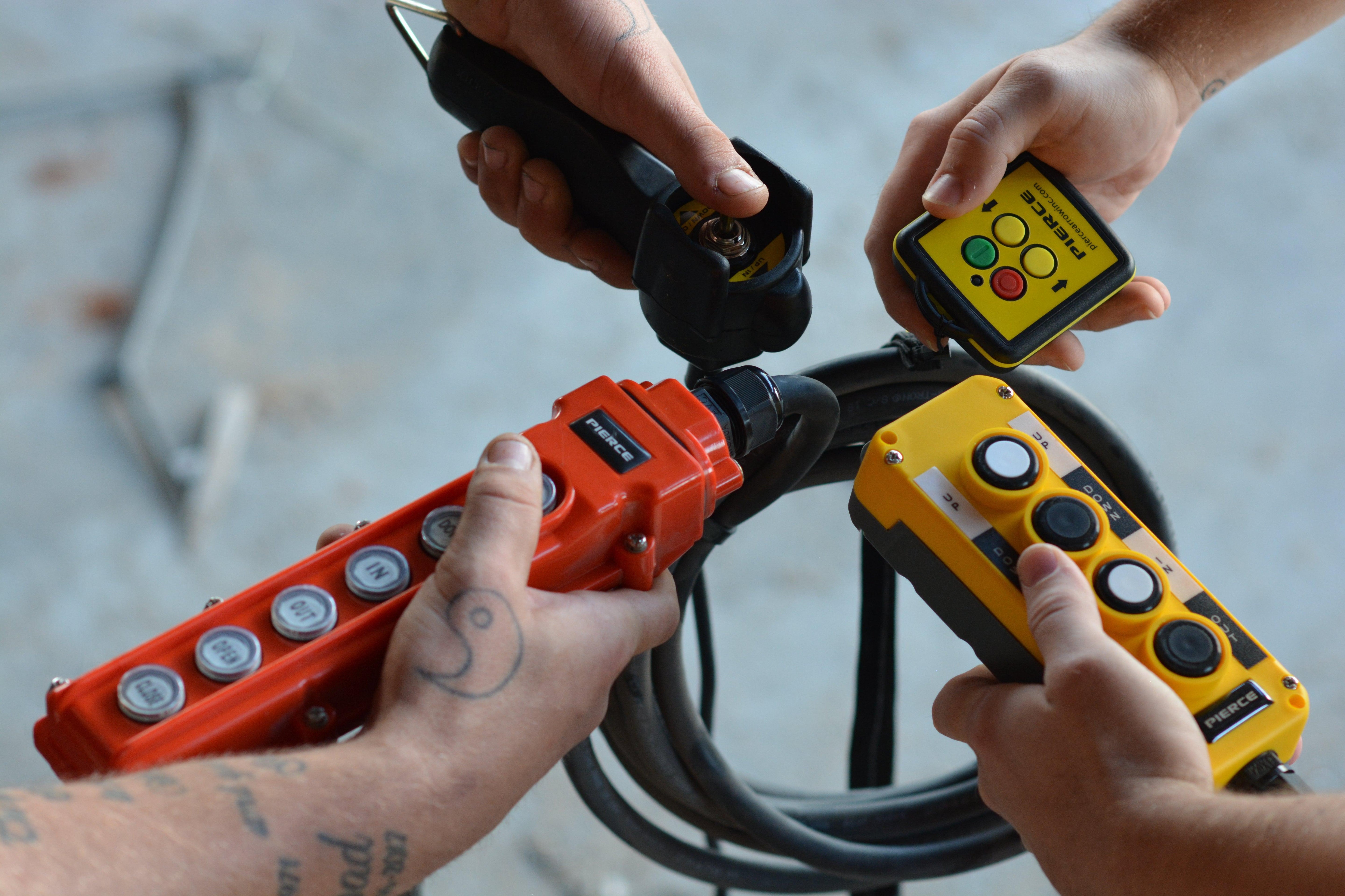
Cab Controls
-
Drill a ½-inch hole in the cab to install the momentary on/off switch (spring-loaded to center).
-
Connect the green wire to the bottom screw and the yellow wire to the top screw on the switch.
-
Reroute the brown wire to the vehicle’s fuse box (ignition-powered position) for key-activated operation.
Part 3: Dump Bed Installation
Hinge Installation
-
Use two hinge pins (or one large pin for added strength) to secure the rear hinges.
Tack Welding
-
Tack weld all components to ensure proper alignment before final welding.
Frame Bracket Installation
-
Bolt L-brackets to the frame behind the overload spring bracket using pre-drilled holes and grade 8 ½-inch bolts with self-locking nuts.
Cross Member Modification
-
Trim the cross member slightly short to facilitate welding to the L-brackets.
Scissor Support Modification
-
Build a bracket to support the scissor assembly in the lowered position to prevent long-term sagging.
Front Frame Hinge Modifications
-
Slide sill supports into the 4-inch channel iron under the bed and secure with two ½-inch grade 8 bolts per side.
Bed Guides
-
Fabricate a cross member in front of the scissor assembly, welding guides to it and bolting it to the frame using existing holes.
-
Countersink bolts to prevent interference with the bed in the lowered position.
Under-Bed Modifications
-
Perform a dry fit to check clearance for cross members or rear hitches. Trim rear hinges if needed, especially for non-standard bed lengths (e.g., 10-foot bed on a 60-inch cab-to-axle truck).
-
Mark and pre-drill holes for sill supports and tie-down brackets before final installation.
Drilling and Trimming
-
Mark hole locations with a paint marker and pre-drill to avoid working under a raised bed.
-
Trim one or two under-bed cross members to accommodate the scissor assembly in the lowered position.
Final Assembly
-
Ensure the bed contacts all four corners, with rear hinges flush against the bed sill and proper front-to-rear alignment.
-
Weld the rear hinges and bolt the front cross member for secure attachment.
Bed Removal for Service
-
Unbolt L-brackets and scissor assembly bolts, then remove rear hinge pins to lift the bed off the truck.
Operational Note
-
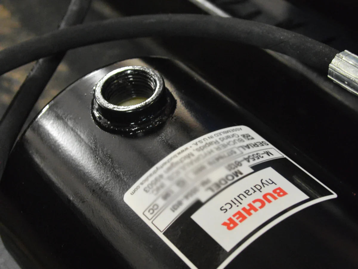
Fill the hydraulic tank only when the bed is lowered, as the oil level drops when the bed is raised in this single-acting system.
Resources
For detailed instructions, refer to:
Contact PIERCE for support or to purchase your Light Duty Dump Bed Kit today!